Brief History of Top Down Design
Bottom–up / top–down Both strategies of information processing and ordering knowledge, used in a variety of fields including engineering made popular by PTC with Creo as early as 1990.
First promoted in the 1970s by IBM researchers Harlan Mills and Niklaus Wirth.
One implementation of top-down design was due to Mil Spec standards. “MilSpecs”, are used to help achieve standardization objectives by the U.S. Department of Defense. Part of that specification basically states that if you don’t own the oceans during war time that you can’t get replacement parts for your war logistics if they are made overseas. Replacement parts must be fabricated in the mainland portion of the United States however Software is a bit different and remains a bit of a grey area. There was also an extreme shortage of software developers, and DOD managers wanted to our source parts of projects called subroutine. The subroutine itself was not top secret. However, all the subroutines compiled together was a secret department of defence project. The main compiled software was the skeleton portion controlling all the other subroutines. Hence, the Top Down design approach was deemed. Parametric Technology Corporation borrowed the term for the early types of top down design known as master merge where one part merged into another all controlled by one master part.
Top down design evolved from designers making assembly references from one part to another, where upon, submission to PDM tools of the time filled up the relatively small hard drives (circa 1993). System Administrators or SYSOP’s, basically managers of working & production PDM database models, became frustrated that the database was filling up quickly because of all the references. They also became frustrated that users created circular references within assemblies. SYSOPS frowned upon using assembly references. For this reason, the top Down part was created. This feature and subsequent part was first new in v20 of Pro/ENGINEER (circa 1998).
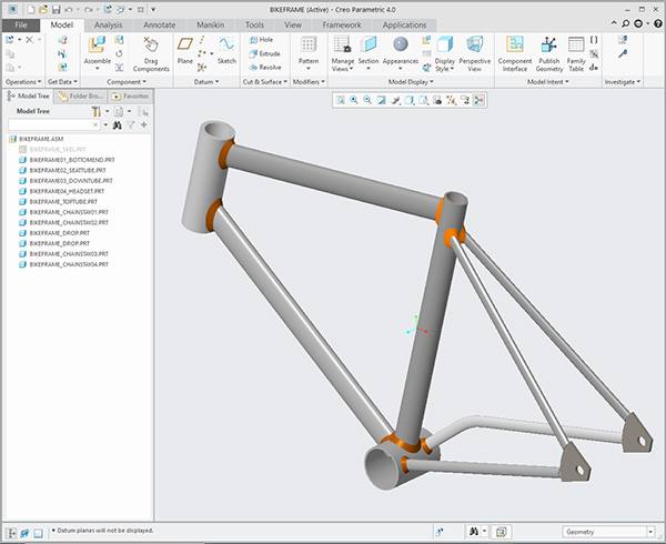
Brief description of Top Down vs Bottom Up design:
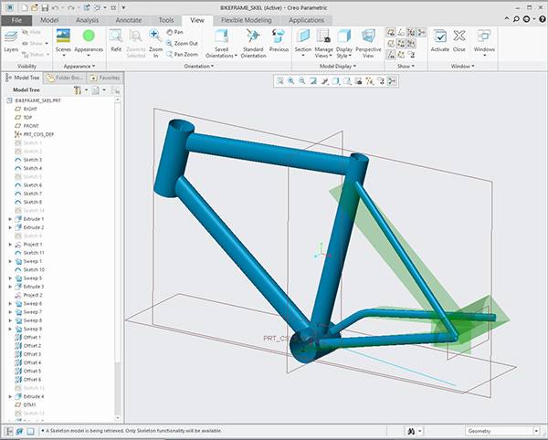
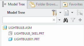
Top-Down design is an approach or methodology to developing products. Top down modeling can allow for one part to control many parts or one part to control movements of other parts; like the skeleton in ones body that controls distance between, and movement of muscle along with body parts. A top down approach can be used to manage movement and fit between parts as well. A skeleton component can be a regular part, or it can be a specific part called a skeleton part. The legitimate skeleton part utilizes a different icon to call out the part; notice the icon in the model tree of an assembly. If a designer can leverage parent child constraints effectively, a top down approach is a great way for making fast changes to your model.
The skeleton part themed approach to Top-down requires users to create parts within assemblies in which parts are all linked together with an ECG feature or an external copied geometry. A key advantage to this method is that less work has to be done when design changes take place because all parts and components will auto-update to specifications driven by the skeleton part, such as shape, dimension, and position. Another advantage is within the assembly all the parts are locate together via one specific default coordinate system. Less experienced designers initially think of locating all the parts together via a default coordinate system as a disadvantage.
Some refer to the ‘Bottom-up’ approach as a more “traditional” method, where the design starts at the component or part level, and then they are inserted within the later created assembly. With this more traditional approach, as changes need to be made to parts, designers have to edit them individually. In this traditional approach designers assemble one part to another.
Think of top down design as a more holistic view of the product scope. The top-down method forces one to take a broader look, and subsequently getting more detailed; starting at the top with the comprehensive project stipulations, then work down to the details.
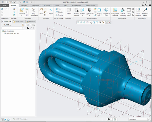
Many different types of top-down design exist with PTC Creo. We might refer to those types as techniques. Each has advantages over another. For example, a skeleton part with external copied geometry via published features offer a more team-oriented approach, while another technique may provide benefits for individual tasks. The latter approach does not require an assembly and created parts within that assembly. Other methods include inheritance features while others use various techniques like published geometry. It’s important to note that there are no specific names to denote each technique and also each designer may picture something very different from what you intend by simply describing these techniques. Most major players such as John Deere, Skil Bosch, Caterpillar, Harley Davidson & Fisher Price have adopted the more teamed approach.
Whether using a teamed approach or not, utilizing PTC Creo’s top-down approach for advanced assemblies has proven to save time and money since it makes it easier to plan out the skeleton of an assembly and changes are effortless.
Visit https://proetools.com/ for more information about our courses and their details.
https://design-engine.com/creo-level-4-advanced-assembly-aax/
Top Down Design VOCABULARY
Boolean – a function within assembly cuts that allows a type of assembly feature operation
Circular References – When part A references Part B in one External Copy reference, then Part B references back to Part A in a different feature. There is always one designer in an organization that consistently creates circular references. It is for this reason that training is so important!
Confidence Drawing: A detail drawing showing dimensions that were required of the designer in a design review meeting. This confidence detailed drawing is less about documentation and more about facilitating a design review meeting. As you mature into becoming a manager from a design engineer you should require team members to bring a confidence drawing to design review. This confidence drawing will make a one-hour meeting 10 minutes. Consider adding a parameter to distinguish if one part is a molded part or another is machined from a molded part.
Dependency – In a top down design environment dependency can be turned off once the product reaches a production status. During the design or development process iteration often works best when dependency is left on.
ECG – External Copy Geometry. An ECG is an external copied geometry from another part into the receiving part. This function forms the basis of a Creo Top down design geometry. Any part can accept an ECG. The main advantage of performing an ECG in Creo vs other utilities is that in Creo we can be specific about what to copy over. Other tools require designers to take the entire part into the other.
Inheritance – A type of top down design feature that will inherent features from other parts or assemblies. This function is often used during top secret clearance projects because others can work on various components through inheritance and an ECG – External Copy Geometry where that specific part may not require top secret clearance. An example of this may be an aircraft; one may be able to see only one part of the aircraft and cannot see the entire aircraft, such as working on landing gear where the bottom front of the aircraft is inherited for a designer to utilize for developing the front landing gear.
Master Merge – An older term often miss used today that describe an early top down design approach for merging one part into another Pre 1998 In this technique the Advanced Assembly module is not required and can still be utilized.
Published Geometry – A work flow that is a feature usually in a skeleton part that pushes out as a reference to individual piece parts. Published Geometry is often published to a footer.
Skeleton Part – A part new in V20 of Pro/ENGINEER (circa 1998) that acts as a driver. Skeleton parts are often a robust set of curves and/or surfaces.
Timestamp – A Creo surface copy that offers one degree of separation for the published geometry to utilize. These are often used by the most experienced user in the company who also creates the skeleton part.
Top Down Design – First created for software programming a top down design approach allowed managers to put a multitude of engineers and designers onto one project. In a top down design approach usually one part drives all the other piece parts of an assembly. Think of the top down design part as a 30 thousand foot view of the product or as a holistic approach to design. In Software programming, a top-down design is the decomposition of a system into smaller parts in order to comprehend its compositional sub-systems.In top-down design, a system’s overview is designed, specifying, yet not detailing any first-level subsystems. Then, every subsystem is refined in greater detail, for example, sometimes dividing into many different levels of subsystem, so that the whole specification is decomposed to basic elements. As soon as these base elements are identified, it is easier to build these elements as computer modules. Once the modules are built, it is effortless to put them together, building the whole system from these individual elements. A top-down design is also known as a stepwise design.
______________________________________________________________________
https://design-engine.com/creo-level-4-advanced-assembly-aax/ Advanced Assembly can be two days or five days
https://design-engine.com/creo-level-12-mechanism-dynamics-intensive/ Two days Mechanism Design
https://proetools.com/creo-weld/ Two days Welding class
https://design-engine.com/creo-level-5-top-down-design/ Two day top down design class
All classes touch upon top down design, however, the two day top down design class covers all possible techniqes that can be ustilized.
